Tuesday, September 29, 2009
Monday, September 28, 2009
Group Discussion
We came to the conclusion that instead of having on central courtyard or individual for each classroom, that it is best to combine them together. We believe, this "circular" strategy will create less hierarchy between the 4 schools (or school as an entirety) by having views between classrooms and a school-wide gathering space at the center. We are also getting a maximum amount of light into each individual classroom (which was one of our goals). In addition we have created a sensible/efficient arrangement of shared and individual spaces.
At this point, we are splitting up again and creating iterations of this arrangement in physical and digital models. These models will also start to get at the darker and lighter programs not mentioned above (i.e. cafe, library, dark labs, light labs, gyms, outdoor rec, etc.).

At this point, we are splitting up again and creating iterations of this arrangement in physical and digital models. These models will also start to get at the darker and lighter programs not mentioned above (i.e. cafe, library, dark labs, light labs, gyms, outdoor rec, etc.).

Tessellations and fractals - in nature, in Escher, in geometries


Escher mastered tessellations - and the idea of one component translating into a second one (as with the swan and fish - or with the scale of the bat). This relates back to our oak tree explorations at the botanical gardens - the shade and light leaves and everything between. With the classrooms, there could be a standard geometry that forms the basic shape and axis. Forces that effect or tessellate the pattern of classrooms and courtyards are the relationships between the 4 schools and sunlight.


As in Escher's work, the same patterns morphing over a landscape or spiral are shown above. Another source to look at as far as translating classrooms that have external components acting on them (4 schools, sunlight).


Examples in geometry that have less variation in comparing them to Escher and Mother Nature's work. They are more static than the previous and don't have another layer of information that begins to deform the repetitive geometry.

A few studies in section and plan

This section shows an arrangement of classrooms, courtyards and light wells in plan and section. The cafe and outdoor recreation spaces are pushed to the south street view for maximum light during the noon/lunch hours - but also to all children to view the city life around them.

These plan and sections show the four schools' classrooms surrounding a common recreation court, in addition to individual courts. There are also larger light wells, instead of a greater number of smaller wells (as in the earlier study).

This shows a section of the shadows created by daylight September 1-May1 at 08:00, 12:00 and 16:00. Posted for its relation to the section and plan studies above.
Shared/Individual/Daylight/Controlled Lighting

A general breakdown of the average lighting for each programmed space - also whether the spaces are "individual" (meaning each of the 4 schools has there own) or shared (meaning the 4 schools share this space).
Sunday, September 27, 2009
Rule #1: twice the amount of outdoor courtyard space compared to classroom size
Rule #2: Individual courtyards for each classroom
Rule #3: One larger, outdoor space shared between 4 schools - as connective tissue/gathering space
Rule #4: To try and get as much light into our space as possible
Rule#5: views allowing interaction between children and city - but still privacy/protection
Rule #6: art studios, music studios, gym, theater, library etc. - shared between 4 schools
Rule #7: upon entering the building, children are in darkest space - as they circulate to classrooms/other program, the building gets lighter
Wednesday, September 23, 2009
Thursday, September 17, 2009
Comparing Plants and Architecture
1. CO2 gained is H2O lost
As you add light, shadow is removed (carving out shadows); in addition, it is a 24 hour cycle, where the light and dark are constantly replacing each other.
2. Daily and Seasonal Cycles (plants change due to changes in their environment): leaves, the sunflower growing towards the sun
3. Multiple uses for one element: Thorns as modified branches, photosynthetic stems (the first plants on earth - evolving from seaweed); the yellow pitcher plant (photosynthetic leaves and bug catcher)
4. Parasitic vines - creeping towards detected shadows (this is where the tree canopy is) - could be thought of a way to carve out shadow.
5. Venation - 40 types found in nature - how do you begin to test which is most efficient - can this relate to movement in an educational institute?
6. The Virus: deforming shapes under specific algorithms - could be thought of a way to being to carve out or morph shadow on the site
7. Lithops: program of building pushed to exterior circumference and capturing light through the openings according to specific day and time of the year (i.e. a playground should be lit fall to spring from noon to one)
8. Slightly varying components that make up the larger whole - similar to the oak tree, which has two general types of leaves: shade and light.
9. Building as a plant in the sense that it is stationary - how can a building "change" during the day and seasons like plants - how light is used is definitely a solution.
10. All elements in plants have a purpose that is part of the form of the larger whole (form and function) - the accordian shape of cacti - expanding after a storm to cary more water.
A time lapse video showing how multiple organisms interact with each other and changes in the environment:
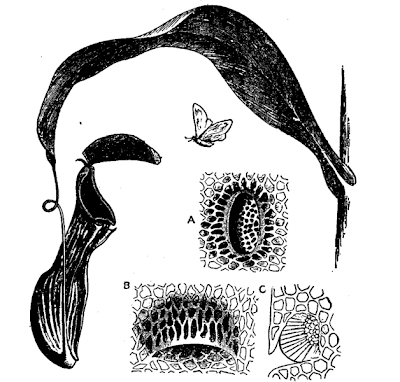
Diagram of a pitcher plant from the Encyclopædia Britannica Eleventh Edition. Pitcher of Nepenthes distillatoria. A: Honey-gland from attractive surface of lid. B: Digestive gland from interior of pitcher, in pocket-like depression of epidermis, opening downwards. C: Traverse section same.
Tuesday, September 15, 2009
"Kenmore Square: A Case Study" By: Paul Lukez

Kenmore Square: across from Charles river and adjacent to MIT - similar to Times Square in it's angular geometries.
Investing new ways of drawings: the spaces between
Who is important? The public's experience through the change in arrangement of space due to position of viewer and time.
The figure ground plans: explored relationships between objects and spaces. Students started with black canvasses and then carved out the space. They found it difficult to relate the drawings to architectural concepts and resorted to the traditional plan.
The Plan: faults are Newtonian - constant speed, steady direction; formulas don't account for unexpected.
Sectional Drawings: an abstraction of viewer's perception of space.
The Students Project and goals of drwaings:
* Design an "information marketplace"
* the drawings were to help in the realization of what spacial relationships and experiences a new building on the site would be produced; with the goals of a permanent building and enhancing existing paths to the site.
Don't be the architect would pursues of "formal explorations and the pursuit of new 'isms.'"
GOAL of graphic explorations: to improve the design process and enrich pubic experience
TO EXPLORE: methods of modeling space to better represent and understand a person's experience of space/time.
Monday, September 14, 2009
Experimenting with Digital Project
Below, is a series of 4 splines that divide the plan into 5 bays. Along the left and right edges are a series of circles connected to certain lines by coincidence. The circle in the upper left hand and lower right hand circles are set to a function so that their radii are always equal. Thus, the screenshots below reveal how this transformation takes place when changing the radius of the two circles to a larger or smaller number.

Below are examples of the transformations with various radii. It seems that the systems limits, before lines begin to cross over are: f (r): 17.00 ≥ r ≥ 7.75

Below, is when the structure begins to push in a third dimension. Each of the three types of arcs shown are constructed in a different manner.

Once connecting the three types of arcs with a spline, a plane can be created. The cutting elements are showing below as well.

For some reason, the limits for the radii to create a surface, was different than over-mutation of the original 5 bay grid. Anything less than r=12, resulted in digital projects not being able to produce a surface.

Subscribe to:
Posts (Atom)